Showing posts with label DIY. Show all posts

Tuesday, 28 March 2023

How to create a Photo-Log or Timelapse with a simple raspberry and an usb webcam

As the title may suggest... Started with a bit of scripting, had a Raspberry pi 3b+ lying around and decided to use it for some time-passing productive activity so I just attached it to a Microsoft LifeCam HD-3000 I had unused, fresh raspbian installed on the SD card and SSH enabled through the raspi-config.

In Summary we used:
  1. Raspberry Pi 3b+
  2. Raspberry power supply
  3. Sandisk microSD card 16gb with raspbian installed on it
  4. usb webcam

So we create the following bash script which I named autoshot.sh I used NANO editor to create this (sudo nano autoshot.sh), script content as follows:

 #!/bin/bash
echo off
DATE=$(date +"%Y-%m-%d")
COUNT=1

while [ $COUNT -le 120 ]
do
        echo Photo: $COUNT
        TIME=$(date +"%H%M%S")
        fswebcam -r 1024x768 -S 10 /home/pi/PROJ/webcam/photos/$DATE-$COUNT-$TIME.jpg
        sleep 30s
        ((COUNT++))
done

And we run as follows and get the following result as well:

pi@raspberrypi:~/PROJ/webcam $ ./autoshot.sh
off
Photo: 1
--- Opening /dev/video0...
Trying source module v4l2...
/dev/video0 opened.
No input was specified, using the first.
Adjusting resolution from 1024x768 to 1280x720.
--- Capturing frame...
Skipping 10 frames...
Capturing 1 frames...
Captured 11 frames in 0.33 seconds. (33 fps)
--- Processing captured image...
Writing JPEG image to '/home/pi/PROJ/webcam/photos/2021-04-05-1-180416.jpg'.
Photo: 2
--- Opening /dev/video0...
Trying source module v4l2...
/dev/video0 opened.
No input was specified, using the first.
Adjusting resolution from 1024x768 to 1280x720.
--- Capturing frame...
Skipping 10 frames...
Capturing 1 frames...
Captured 11 frames in 0.33 seconds. (33 fps)
--- Processing captured image...
Writing JPEG image to '/home/pi/PROJ/webcam/photos/2021-04-05-2-180447.jpg'.

Then we just need to either use the raspbian GUI or setup a samba shared folder on the raspberry to grab the photos from a windows machine, for example.

Monday, 13 December 2021

Custom boot on chromebox / chromebook

First, massive thanks and apraise to the creator of https://mrchromebox.tech/#home Over there you can find all info needed to perform this changes.

In my case I wish to transform this small workstation / thin client into a media server for the living room as its silent, power efficient (20~60 watts depending on task) and looks neat finished

We will be installing Kodi on this one but same steps until the OS install can be followed for almost any other OS. I can confirm that OpenSUSE works flawless even on the less powerful i3 models.

Step 1 - Remove the Write-Protect restriction screw

Two examples below. Chromeboxes Asus CN60 or CN62 on the left, Chromebook HP Chromebook 13 G1 on the right:
  

Step 2 - Booting to Developer mode

Entering Developer Mode requires you to first boot into Recovery Mode. To start in recovery mode, two methods depending if the device its a chromebook or a chromebox
  • Chromebook: You have to you have to turn on your machine with a key combination [ESC+Refresh+Power]
  • Chromebox: Holding the reset button with a pin and pressing once the power button.
Once turned on as above, the next screen should say "Chrome is missing or damaged"
You are now in Recovery mode boot, Press [CTRL+D] to bring a confirmation window, press the reset button on the side of the chromebox again and it will prompt you with "OS verification is OFF"
Dont follow the window instruction and press [CTRL+D] again to reboot, this time in Developer mode.
 
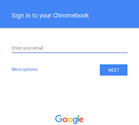
You might be prompted with a normal login screen with a "Enable debugging features" click there, then "Proceed", set a root password (I used 'chronos'), and click on "Enable".
Once rebooted, the device is on developer mode, just wait for it to load the chromeOS.

Step 3 - Install modified firmware. Open-source SeaBIOS

Once in the sign in screen as per last step, press [CTRL+ALT+F2] to bring up a terminal / command line. On the terminal, just type chronos to sign as the root user (no password).

Step 3.1 - To download and run this script under ChromeOS, from a terminal/shell type:
(new version)
cd; curl -LO mrchromebox.tech/firmware-util.sh && sudo bash firmware-util.sh
 
(old version)
cd; curl -LO mrchromebox.tech/firmware-util.sh

sudo install -Dt /usr/local/bin -m 755 firmware-util.sh

sudo firmware-util.sh

We will then be presented with a screen similar to the following with our respective Device model.

Step 3.2 - Proceed with the script
Just need to install the UEFI BIOS firmware to allow install of any OS*, so press 2 and ENTER.
Upon confirmation, Y and ENTER again.
Further confirmation Y and ENTER again.
And finally Y / n depending if you want to make a backup of the current firmware.

If all good the terminal should return a "Full ROM firmware successfully installed/updated" with a reminder of a possible long first boot thereafter.

Press ENTER to be redirected to the main menu of the script and press R and ENTER to reboot.

Step 4 - Install a different OS

Grab an usb pendrive and image it using Rufus with your OS iso of choice...

To be updated......
......
...
.

Tuesday, 18 July 2017

Teclado DIN a usb [Discontinued]


Este es uno de mis primeros bricos, una conversión de conector DIN a conector usb en un teclado mecánico Chicony KB-5192.

El primer paso fué el retirar un par de tornillos que tiene en la parte de abajo

Al separar las dos partes que componen la carcasa del teclado dejamos al descubierto la placa con los switch de cada tecla, los LEDs de estado y el cable que conecta la placa del teclado al pc por medio de un conector DIN. En las fotos podéis ver el DIN en comparación a un también antiguo ps/2.


conector DIN vs ps/2

Hecho esto, las siguientes partes constan de la búsqueda de información sobre ésta conversión de interfaces. Casi no hay información y la que hay, sobre modelos IBM o Cherry, así pues por 3€ desde ebay:

Conversor activo de ps/2 a usb

Pineado

Hacemos la pertinente conversión de pines de DIN a ps/2 y soldamos al chip siguiendo los siguientes esquemas de pines:


[Discontinuación del proyecto,,,]

El motivo es que el adaptador usado parece no convertir perfectamente los tiempos de las pulsaciones, no aceptando las pulsaciones largas, por lo que tenemos un teclado maravilloso para escribir, pero no para jugar.

Probablemente un buen proyecto para arduino, ya se verá.